Product Model: IOM12682
Overview:
The product adopts the mainstream ARM 32-bit microprocessor that supports Modbus RTU for rapid expansion of controller I/O modules.
Protocol specification:
Supports Modbus RTU protocol for fast network connection with controllers that support the protocol and rapid I/O port expansion. Please refer to the instruction of Modbus RTU test tool for details.
Main Parameter:
| Processor |
32 bit |
| Clock Frequency |
72MHz |
| Memory |
64KB flash, 20KB random access memory |
| Power |
AC/DC 12~24V |
| Communication |
Modbus RTU(9600/8/1/None, address 1) |
| Digital Input |
Support dry contact input |
| Digital Output |
Supports dry contact output, the maximum is 220V/5A |
| Analog Input |
Supports 0-10V, 0-20mA (AD 14bit) |
| Analog Output |
Supports 0-10V, 0-20mA (DA 12bit) |
|
Product Model |
BI/DI |
BO/DO |
AI |
AO |
|
IOM12682 |
12 |
6 |
8 |
2 |
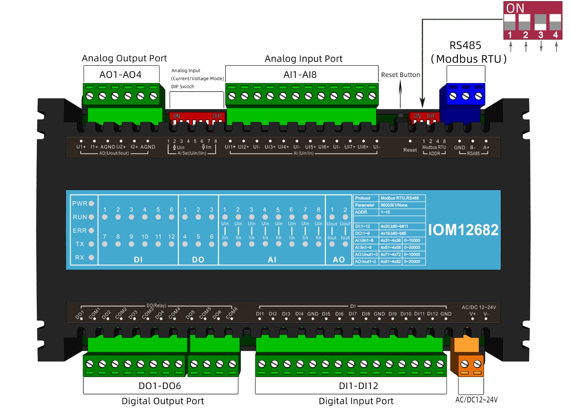
Register Definition Description:
1. Register corresponds to Modbus RTU
BI/DI---Input Status(0x02)
|
BI/DI Register Address |
BI/DI |
Description |
|
10001 |
1 |
Digital Input Port |
|
10002 |
2 |
Digital Input Port |
|
10003 |
3 |
Digital Input Port |
|
10004 |
4 |
Digital Input Port |
|
10005 |
5 |
Digital Input Port |
|
10006 |
6 |
Digital Input Port |
|
10007 |
7 |
Digital Input Port |
|
10008 |
8 |
Digital Input Port |
|
10009 |
9 |
Digital Input Port |
|
10010 |
10 |
Digital Input Port |
|
10011 |
11 |
Digital Input Port |
|
10012 |
12 |
Digital Input Port |
BO/DO―Holding Register(0x01/0x05)
|
BO/DO Register Address |
BO/DO |
Description |
|
00001 |
1 |
Digital Output Port |
|
00002 |
2 |
Digital Output Port |
|
00003 |
3 |
Digital Output Port |
|
00004 |
4 |
Digital Output Port |
|
00005 |
5 |
Digital Output Port |
|
00006 |
6 |
Digital Output Port |
Register corresponds to Modbus RTU
Voltage and current (choose one)
AI---Input Register(0x03)
|
AI Port |
Voltage Register Address |
Voltage corresponding value |
Current Register Address |
Current corresponding value |
|
1 |
40031 |
0~10V=0~10000 |
40051 |
0~20mA=0~20000 |
|
2 |
40032 |
0~10V=0~10000 |
40052 |
0~20mA=0~20000 |
|
3 |
40033 |
0~10V=0~10000 |
40053 |
0~20mA=0~20000 |
|
4 |
40034 |
0~10V=0~10000 |
40054 |
0~20mA=0~20000 |
|
5 |
40035 |
0~10V=0~10000 |
40055 |
0~20mA=0~20000 |
|
6 |
40036 |
0~10V=0~10000 |
40056 |
0~20mA=0~20000 |
|
7 |
40037 |
0~10V=0~10000 |
40057 |
0~20mA=0~20000 |
|
8 |
40038 |
0~10V=0~10000 |
40058 |
0~20mA=0~20000 |
AO―Holding Register(0x03/0x06)
|
AO Port |
Voltage Register Address |
Voltage corresponding value |
Current Register Address |
Current corresponding value |
|
1 |
40071 |
0~10V=0~10000 |
40081 |
0~20mA=0~20000 |
|
2 |
40072 |
0~10V=0~10000 |
40082 |
0~20mA=0~20000 |
|
AO Register Address |
AO Port |
Description |
|
40001 |
--- |
Device Address: 1(1~15) |
|
40002 |
--- |
BDT: 9600 (2.4K/4.8K/9.6K/19.2K/115.2K) |
|
40003 |
--- |
Check bit: None(0-none;1-odd;2-even) |
Frequently asked questions:
1.ModbusRTU common question:
Q ① : What is the default communication parameter for the module?
A ① : The default communication parameters of the ModbusRTU module: baut rate 9600, data-bit 8, stop-bit 1, no parity, and device ID is 1.
Q ② : How to modify the communication parameters of the module?
A ② :Use third-party software Modbus Poll, follow chapter “3.0 Description of Definition for Registers”, Read the data from registers 40001 and 40002, which represent device addresses (1-15) and communication baud rate of 9600. Modify the module communication parameters according to the description in the "Instructions" column. After power failure and restart, the set parameters take effect. (Station number 40001 displays the station number set by the current dip switch. If software is required to set the station number, the dip switches 1/2/3/4 must be placed in the OFF position.)
Q③: How to modify the device ID?
A③: Refer to the table below for the internal dial of the hardware (binary dial code).The dip switch has 4 bits, each representing a numerical value. When pushed to the OFF position, it is set to 0. When turned ON, it represents 1, 2, 4, and 8 in sequence. When turned ON, it represents the sum of numerical values, which equals the address code of the device. If the device ID is set to "11", dialing codes 1, 2, and 4 will push it to the ON position, and dialing code 3 will push it to the OFF position, which is equivalent to 1+2+8=11. Note: The maximum address code is 15.
|
Device ID |
1 |
2 |
3 | ,, , ,
5 |
6 |
7 |
8 |
9 |
10 |
11 |
12 |
13 |
14 |
15 |
|
Dial |
1 |
2 |
1+2 |
3 |
1+3 |
2+3 |
1+2+3 |
4 |
1+4 |
2+4 |
1+2+4 |
3+4 |
1+3+4 |
2+3+4 |
1+2+3+4 |
Q④: How to forcibly reset the baud rate of this I/O module to its default value?
A④ : Activate the module's hardware reset button (typically labeled Reset). This action immediately restores the baud rate to 9600, ensuring rapid reset of the communication link to its initial state.
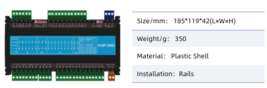
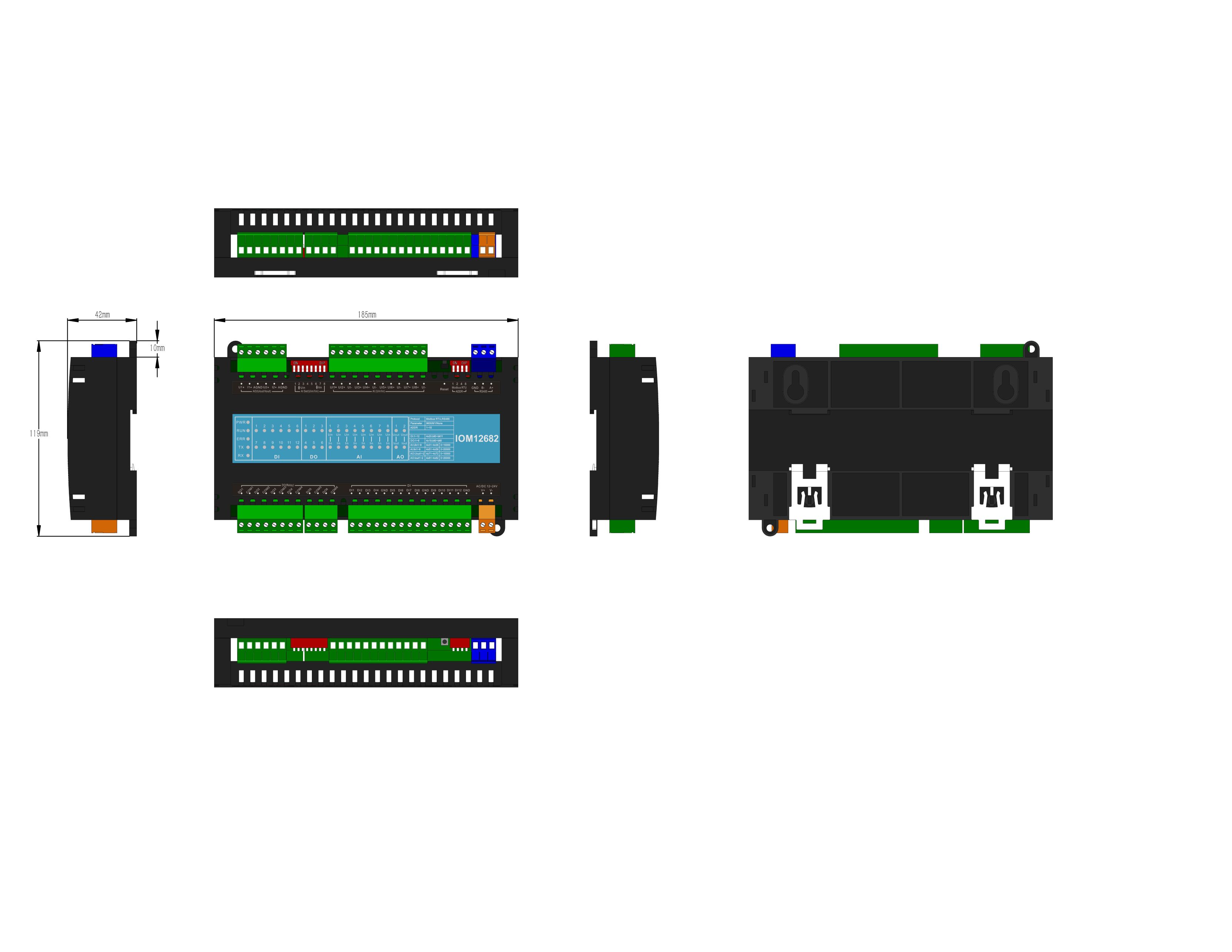
Dimension :
,
|