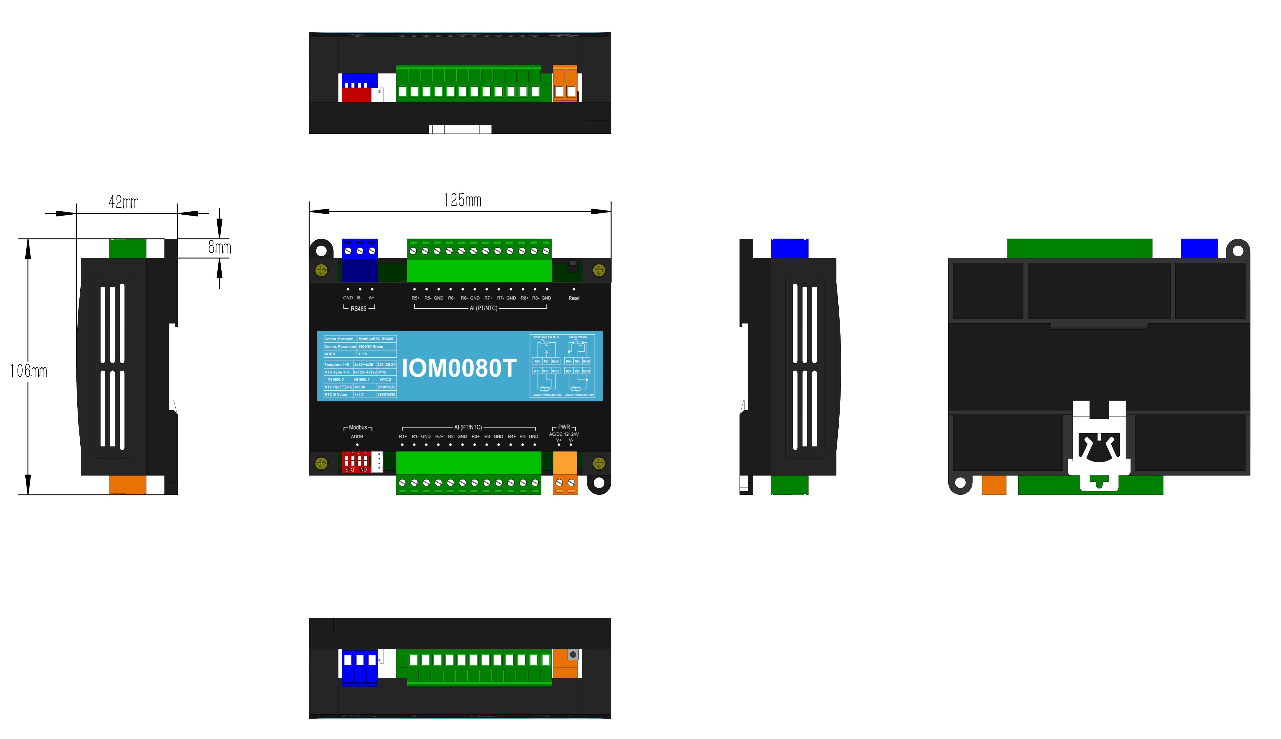
Product Model: IOM0080T
Overview:
The product adopts the mainstream ARM 32-bit microprocessor that supports Modbus RTU protocols for rapid expansion of controller I/O modules.
Protocol Description:
Supports Modbus RTU protocol for fast network connection with controllers that support the protocol and rapid I/O port expansion. Please refer to the instruction of Modbus RTU test tool for details.
RTD type of thermal resistance: Pt1000,Ni1000,NTC,Pt100,Cu100,Cu50。
Core Parameter:
| Processor |
32 bit |
| Clock Frequency |
72MHz |
| Memory |
64KB flash, 20KB random access memory |
| Power |
AC/DC 12~24V |
| Communication |
Modbus RTU(9600/8/1/None, Address 1) |
| RTD type of thermal resistance |
SPt1000,Ni1000,NTC,Pt100,Cu100,Cu50 |
| Temperature resolution |
SPt1000,Ni1000,NTC,Pt100,Cu100,Cu50 |
| Sampling rate |
Default: 0.15s per channel with 8-channel cyclic scanning; configurable filter length. |
Model Number Description:
|
Model Number |
BI/DI |
BO/DO |
AI |
AO |
|
IOM0080T |
0 |
0 |
8 |
0 |
Product display :

Register definition specification:
1.Register corresponds to Modbus RTU
Voltage and current(choose one)
AI---Input Register(0x03)
|
RTD temperature Register Address |
RTD type register address |
AI Port |
Description |
|
40022 |
40122 |
1 |
RTD Input Port |
|
40023 |
40123 |
2 |
RTD Input Port |
|
40024 |
40124 |
3 |
RTD Input Port |
|
40025 |
40125 |
4 |
RTD Input Port |
|
40026 |
40126 |
5 |
RTD Input Port |
|
40027 |
40127 |
6 |
RTD Input Port |
|
40028 |
40128 |
7 |
RTD Input Port |
|
40029 |
40129 |
8 |
RTD Input Port |
AO---Holding Register(0x03/0x06)
|
AO Register Address |
AO Port |
Description |
|
40001 |
-- |
Device Address: 1(1~15) |
|
40002 |
-- |
BDT: 9600 (2.4K/4.8K/9.6K/19.2K/115.2K ) |
|
40003 |
-- |
Check bit: None(0-none;1-odd;2-even) |
Register Description:
一、RTD Temperature Registers: Address Range: 4x22 to 4x29 (Short type,range: -32,768 to 32,767).
Stores linearized temperature values (unit: 0.1°C) from RTD sensors connected to Channels 1–8.
Scaling: Register value = actual temperature × 10.
Examples:
Register value 253 → 25.3°C
Register value -128 → -12.8°C.
二、RTD Type Configuration Registers:
1、Address Range: 4x122 to 4x129 (Short type, range: -32,768 to 32,767).
Configures RTD sensor types for Channels 1–8. Each input channel supports individual configuration of sensor types.
Mapping: The register value corresponds to the RTD type as follows:
|
Set value |
RTD Type |
range |
|
0(Default) |
Pt1000(Default) |
Min=-50.0℃ |
Max=300.0℃ |
|
1 |
1 |
Min=-50.0℃ |
Max=250.0℃ |
|
2 |
2 |
Min=-55.0℃ |
Max=125.0℃ |
|
3 |
3 |
Min=-200.0℃ |
Max=660.0℃ |
|
4 |
4 |
Min=-50.0℃ |
Max=150.0℃ |
|
5 |
5 |
Min=-50.0℃ |
Max=150.0℃ |
Note1: NTC mode requires setting R@25℃ and B value
2、Address 4x130 (Short type, range: -32,768 to 32,767)
Function: NTC R-value (25°C) configuration, unit: kΩ.
Scope: Shared by Channels 1–8. Valid only for NTC-type inputs.
Configurable values include:
5:5K NTC
10:10K NTC(Default)
15:15K NTC
20:20K NTC
3、 Address 4x131 (Short type, range: -32,768 to 32,767)
Function: NTC Beta value (B-constant) configuration.
Scope: Shared by Channels 1–8. Valid only for NTC-type inputs.
Configurable values include:
3950(Default)
3380
3435
3470
Frequently asked questions:
1.ModbusRTU common question:
Q ① : What is the default communication parameter for the module?
A ① : The default communication parameters of the ModbusRTU module: baut rate 9600, data-bit 8, stop-bit 1, no parity, and device ID is 1.
Q ② : How to modify the communication parameters of the module?
A ② :Use third-party software Modbus Poll, follow chapter “3.0 Description of Definition for Registers”, Read the data from registers 40001 and 40002, which represent device addresses (1-15) and communication baud rate of 9600. Modify the module communication parameters according to the description in the "Instructions" column. After power failure and restart, the set parameters take effect. (Station number 40001 displays the station number set by the current dip switch. If software is required to set the station number, the dip switches 1/2/3/4 must be placed in the OFF position.)
Q③: How to modify the device ID?
A③: Refer to the table below for the internal dial of the hardware (binary dial code).The dip switch has 4 bits, each representing a numerical value. When pushed to the OFF position, it is set to 0. When turned ON, it represents 1, 2, 4, and 8 in sequence. When turned ON, it represents the sum of numerical values, which equals the address code of the device. If the device ID is set to "11", dialing codes 1, 2, and 4 will push it to the ON position, and dialing code 3 will push it to the OFF position, which is equivalent to 1+2+8=11. Note: The maximum address code is 15.
|
Device ID |
1 |
2 |
3 |
4 |
5 |
6 |
7 |
8 |
9 |
10 |
11 |
12 |
13 |
14 |
15 |
|
Dial |
1 |
2 |
1+2 |
3 |
1+3 |
2+3 |
1+2+3 |
4 |
1+4 |
2+4 |
1+2+4 |
3+4 |
1+3+4 |
2+3+4 |
1+2+3+4 |
Q④: How to forcibly reset the baud rate of this I/O module to its default value?
A④ : Activate the module's hardware reset button (typically labeled Reset). This action immediately restores the baud rate to 9600, ensuring rapid reset of the communication link to its initial state.
Dimension :

|